A building project can feel like a conversation in a foreign language. Builders, engineers, and architects all rely on a shared “script”: a coordinated set of drawings. At the center are a few essential Plan types and once you understand them, the entire project becomes far more legible, and the conversation is much easier to follow.
Your Google View of Home: The Site Plan
Think of the site plan as a bird’s-eye view of your property. It shows property lines, the footprint of the house, and how any additions sit within the lot. Typically prepared by a civil engineer or land surveyor – with input from the architect – it’s critical for securing municipal approvals. Zoning requirements such as setbacks (how close structures can be to property lines) are clearly illustrated, along with easements and other constraints. More detailed versions may also include driveways, walkways, grading, landscaping, and existing vegetation. In short, the site plan explains how your project fits on the land.
What’s the Plan? The Floor Plan
The floor plan is the primary drawing for understanding the building itself. Technically, it’s a horizontal “slice” through the structure, usually about 4 feet above the floor, viewed from above. It shows walls, doors, windows, cabinetry, and fixed elements like plumbing fixtures.
Floor plans are intentionally diagrammatic. They rely on standard symbols rather than detailed construction depictions. The emphasis is on dimensions, spatial relationships, and circulation – not every stud or fastener. Notes and callouts link to more detailed drawings elsewhere in the set.
If a floor plan feels abstract, that’s normal. It’s also essential. Clear communication here is critical, so if something doesn’t make sense, ask. Architects can provide enlarged plans, 3D views, or diagrams to clarify intent.
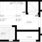
What’s Up? The Ceiling Plan
Flip the same horizontal slice and look upward – that’s the reflected ceiling plan. It maps lighting, switches, outlets, and ceiling features such as soffits, crown molding, or paneling. Like the floor plan, it’s a coordination tool rather than a fully detailed rendering.
This drawing is especially important for electricians and lighting designers, guiding fixture placement and circuiting. It also helps align ceiling elements with the rooms below, ensuring everything works together spatially and visually.
Why It Matters
Together, these plans form the backbone of a construction document set. They guide approvals, pricing, coordination, and ultimately construction. More importantly, they are the common language of your project team. As a homeowner, understanding what each plan communicates – and what it doesn’t – helps you make informed decisions and avoid surprises. When in doubt, ask for clarification. A well-understood drawing set is one of the strongest predictors of a successful project.